int S2= 7; //Color sensore pin S2 to Arduino pin 7
int S3= 8; //Color sensor pin S3 to Arduino pin 8
int outPin = 4; //Color Sensor OUT to Arduino pin 4
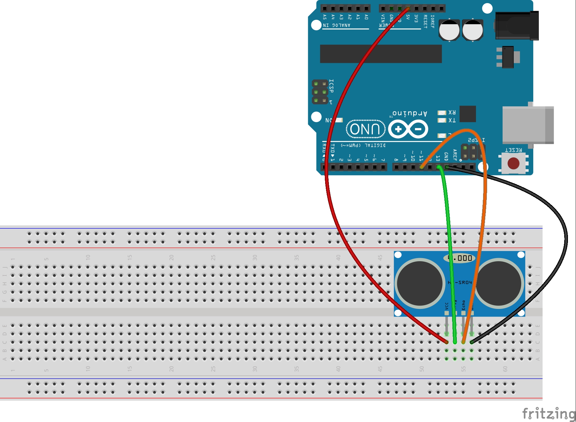
int trigPin=13; //Ultrasonic Sensor Trig pin connected to Arduino pin 13
int echoPin=11; //Ultrasonic Sensor Echo pin connected to Arduino pin 11
int rColorStrength; //measured strength of red color
int gColorStrength; //measured strength of green color
int bColorStrength; //measured strength of blue color
unsigned int pulseWidth; //for measuring color strength using pulseIn command
float pingTime; //time for ping to travel from sensor to target and return
float targetDistance; //Distance to Target in inches
float speedOfSound=776.5; //Speed of sound in miles per hour when temp is 77 degrees.
void setup() {
// put your setup code here, to run once:
Serial.begin(115200); //turn on serial port
pinMode(S2, OUTPUT); //S2 and S3 are outputs and used to tell
pinMode(S3, OUTPUT); //arduino which color to measure
pinMode(outPin, INPUT); //This is the pin we read the color from
pinMode(trigPin, OUTPUT); //Ultrasonic Trig Pin is an output
pinMode(echoPin, INPUT); //Ultradoinic Echo Pin is an input
}
void loop() {
//Lets start by reading Red Component of the Color
// S2 and S3 should be set LOW
digitalWrite(S2, LOW);
digitalWrite(S3, LOW);
pulseWidth = pulseIn(outPin, LOW); //Measure raw pulsewidth coming from color sensor outpin
rColorStrength = pulseWidth/400. -1; //normalize number to number between 0 and 255
rColorStrength = (255- rColorStrength); //reverse so that large number means strong color
//Lets read Green Component of the Color
// S2 and S3 should be set HIGH
digitalWrite(S2, HIGH);
digitalWrite(S3, HIGH);
pulseWidth = pulseIn(outPin, LOW); //Measure raw pulsewidth coming from color sensor outpin
gColorStrength = pulseWidth/400. -1; //normalize number to number between 0 and 255
gColorStrength = (255- gColorStrength); //reverse so that large number means strong color
gColorStrength=gColorStrength + 2;
//Lets read Blue Component of the Color
// S2 and S3 should be set LOW and HIGH Respectively
digitalWrite(S2, LOW);
digitalWrite(S3, HIGH);
pulseWidth = pulseIn(outPin, LOW); //Measure raw pulsewidth coming from color sensor outpin
bColorStrength = pulseWidth/400. -1; //normalize number to number between 0 and 255
bColorStrength = (255- bColorStrength); //reverse so that large number means strong color
//Now we need to exagerate the colors because readings from color sensor
//are all too close together. Algorithm that appears to work is to
//take the strongest color and set to 255, take the weakest color
//and set to zero, and then take the middle color and reduce its
//value by 2. That is what this next segment of code does.
if(rColorStrength>gColorStrength && gColorStrength>bColorStrength) {
rColorStrength = 255;
gColorStrength = gColorStrength/2;
bColorStrength = 0;
}
if(rColorStrength>bColorStrength && bColorStrength>gColorStrength) {
rColorStrength = 255;
bColorStrength = bColorStrength/2;
gColorStrength = 0;
}
if(gColorStrength>rColorStrength && rColorStrength>bColorStrength) {
gColorStrength = 255;
rColorStrength = rColorStrength/2;
bColorStrength = 0;
}
if(gColorStrength>bColorStrength && bColorStrength>rColorStrength) {
gColorStrength = 255;
bColorStrength = bColorStrength/2;
rColorStrength = 0;
}
if(bColorStrength>rColorStrength && rColorStrength>gColorStrength) {
bColorStrength = 255;
rColorStrength = rColorStrength/2;
gColorStrength = 0;
}
if(bColorStrength>gColorStrength && gColorStrength>rColorStrength) {
bColorStrength = 255;
gColorStrength = gColorStrength/2;
rColorStrength = 0;
}
//Now lets measure distance to target from the ultrasonic sensor
digitalWrite(trigPin, LOW); //Set trigger pin low
delayMicroseconds(2000); //Let signal settle
digitalWrite(trigPin, HIGH); //Set trigPin high
delayMicroseconds(15); //Delay in high state
digitalWrite(trigPin, LOW); //ping has now been sent
delayMicroseconds(10); //Delay in low state
pingTime = pulseIn(echoPin, HIGH); //pingTime is presented in microceconds
pingTime=pingTime/1000000; //convert pingTime to seconds by dividing by 1000000 (microseconds in a second)
pingTime=pingTime/3600; //convert pingtime to hours by dividing by 3600 (seconds in an hour)
targetDistance= speedOfSound * pingTime; //This will be in miles, since speed of sound was miles per hour
targetDistance=targetDistance/2; //Remember ping travels to target and back from target, so you must divide by 2 for actual target distance.
targetDistance= targetDistance*63360; //Convert miles to inches by multipling by 63360 (inches per mile)
//Now lets print our data to the serial monitor all on one line divided by commas.
Serial.print(rColorStrength);
Serial.print(" , ");
Serial.print(gColorStrength);
Serial.print(" , ");
Serial.print(bColorStrength);
Serial.print(" , ");
Serial.println(targetDistance);
delay(150);
}