Category Archives: Arduino 9-Axis IMU Totorials

9-Axis IMU LESSON 6: Determine Tilt From 3-axis Accelerometer

BNO055
Adafruit BNO055 9-axis Sensor Connected to an Arduino Nano

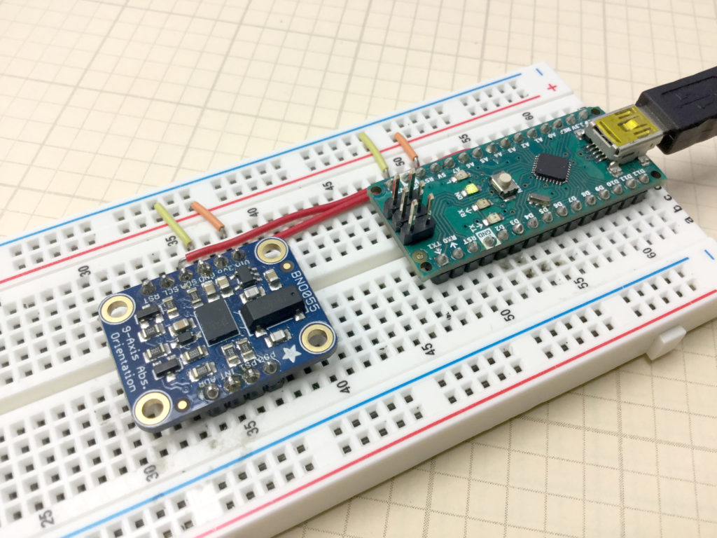
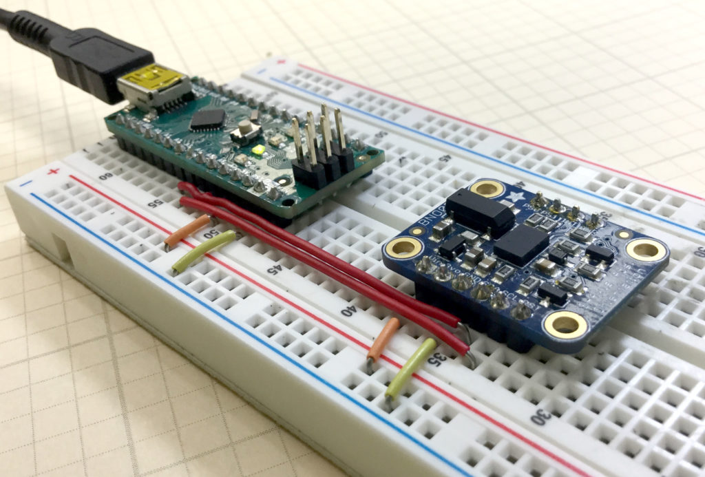
This lesson shows you some of the simple math, that will allow you to approximate tilt angle from a three axis accelerometer. In this entire series of lessons, we are using the BNO055 9-axis sensor connected to an Arduino Nano. It is possible to approximate tilt along the x-axis and tilt along the y-axis. These could roughly be considered to be like the Euler Angles of Pitch and Roll. It should be noted that the approximations are reasonable for tilt angles less than 45 degrees. Also note, that in this simple demonstration, real acceleration will be interpreted as tilt, hence the system will incorrectly interpret motion as tilt. Because of this, this approach should not be used on things like drones or other moving systems. It is just for simple demonstration purposes.

The code developed in the video above is included below for your convenience.

The code below is for demo purposes only, and should not be used in any real applications. It just demonstrates how to work with this sensor in benchtop presentations.


9-Axis IMU LESSON 5: Calibrating the BNO055 9-axis Inertial Measurement Sensor

BNO055 IMU
Our 9-axis BNO055 9-axis sensor connected to our Aurduino Nano

In this lesson we show you how to get a clean calibration on your BNO055 9-axis sensorIn the video below we take you through the coded needed to calibrate the sensor, and a simple technique to quickly get the system properly calibrated.

The code developed in this video will be used in future lessons, and is included below:

The code below is for demo purposes only, and should not be used in any real applications. It just demonstrates how to work with this sensor in benchtop presentations.


9-Axis IMU LESSON 4: Plotting Serial Data from Arduino with Control of Axis Scale

As this project continues it is very important for us to be able to quickly and easily plot data streaming from the sensor. The Arduino Serial Plotter has some real limitations, we recommend a simple “Serial Plotter” tool that can be downloaded. In this video we take you step by step through the download and installation process, and then an overview of how to use the tool.

9-Axis IMU LESSON 3: Understanding How Accelerometers Work

Accelerometer
This photo shows a conceptual schematic of how an accelerometer works.

In this lesson we describe how the acceleromters on chips like the Adafruit BNO055 work. They work based on microscopic masses suspended on springs on the chip. As the chip moves, the suspended masses respond to the motion, and the gaps between the suspended masses and the substrate changes. The chips detect these changes in position by monitoring the capacitance between the suspended mass and the substrate, or between the suspended masses and carefully designed interdigitated fingers between the mass and the substrate. C=eA/d, e is the dielectric constant of the material, A is the area of the capacitor, and d is the gap between the two capacitor plates. Changes in measured capacitance come from either a change in A or a change in d. Both d and A change in response to motion, so by monitoring the capacitance of the suspended mass, acceleration can be inferred. The video below explains clearly how this works.

Code for Getting Raw Acceleration Data from the BNO055 9-axis Inertial Measurement Sensor.

The code below is for demo purposes only, and should not be used in any real applications. It just demonstrates how to work with this sensor in benchtop presentations.

IMUl 9-Axis IMU LESSON 2: Connecting and Getting Raw Data from the BNO055 9-Axis Sensor

BNO055
Adafruit BNO055 9-axis Sensor Connected to an Arduino Nano

In this tutorial we show you how to get raw sensor data from the Adafruit BNO055 9-axis sensor. We are using an Arduino Nano, since it allows for neat, compact builds on a breadboard. The sensor can provide acceleration along x,y and z axis, rotational velocities around x, y and z axis, as well as the strength of the earth’s magnetic vector along the sensor’s x, y, and z axis. The sensor can do a lot more than this, but to get things started, we will show you how to get these raw sensor readings from the device.

The video shows you how to connect the sensor, and below we include the code developed in the video. We strongly suggest you type the code in yourself, as you follow along with the video. You will never learn how to develop projects on your own, if you just copy and paste my code.

The code below is for demo purposes only, and should not be used in any real applications. It just demonstrates how to work with this sensor in benchtop presentations.