Arduino Tutorial 50: How to Connect and Use the DHT11 Temperature and Humidity Sensor

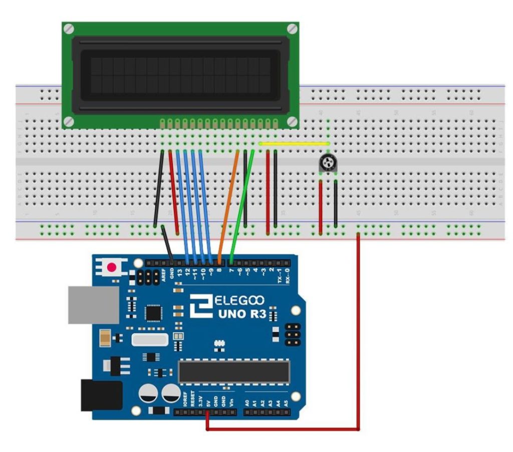
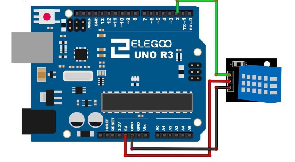
In this lesson we show how to measure Temperature and Humidityusing the DHT11 sensor. This is a relatively simple sensor to use, but you will have to download and install a library. In our earlier lessons, we have used libraries before, but this is the first time you will have to download a library. The library I used was downloaded from HERE. The video explains in detail how to install the library, but in a nutshell you download the library from clicking the link on that page. Then you need to open the downloaded zip file, and then drag and drop the contents of the zip file to your desktop. Next you must determine where your arduino library folder is. You can do that by going to the arduino IDE, and under “file” select preferences. This will show you your “Sketchbook Location”, and that folder will contain your libraries folder. The folder you dragged and dropped onto your desktop should be dragged and dropped now into this library folder. The video shows you how to do this if this description is not clear. Now you will need to connect the sensor, according to this schematic:

DHT11 Sensor
Connection schematic for the DHT11 Temperature Sensor.

The video develops the code to use this sensor step-by-step, but the code is included below for your convenience.


Arduino Tutorial 49: How to Build a Simple Calculator with LCD Display

In this lesson we show you our solution to the assignment in Lesson 48 to build a simple calculator with an LCD Output. The video steps you through the project build step-by-step.

In the project, the following schematic is used.

Arduino LCD Schematic
This schematic will allow you to connect the LCD to the Arduino.

If you need the kit we are using in this series of lessons, you can get it HERE.

And this is the code developed in the video.


Arduino Tutorial 48: Connecting and Using an LCD Display

LCD Arduino
LCD connected to an Arduino.

It is often times useful to “un-tether” your arduino from your desktop PC, in order to have a system you can walk around with, and interact with the real world. One of the first steps in making this happen is to have some sort of display on your arduino project. In this lesson, we show you how to connect and program your project to be able to display simple messages on the LCD. This is a schematic diagram of how to connect the arduino to an LCD display. This will work for the LCD in the Elegoo Kit. Many LCD displays in fact share this same connection schematic.

Arduino LCD Schematic
This schematic will allow you to connect the LCD to the arduino.

The details are provided in the following video.


Below is the code we developed in the video.


9-Axis IMU LESSON 26: Understanding PID Control systems with Arduino


In this lesson we use our BNO055 9-axis sensor, and our pan-tilt servo mount to create a self-leveling platform based on a classic PID control system. The video takes you step by step through the theory behind a PID controller, and then demonstrates a practical example in hardware. In the video we develop the code below.


Arduino Tutorial 47: Binary and Hexadecimal Bit Flipper

In this lesson we explore how to create a Binary or Hexadecimal Bit Flipper. From our earlier lessons you see we can visually represent Hexadecimal or Binary numbers with a series of LED, with an on LED representing a “1” and an off LED representing a “0”. In programming and circuit applications, it is sometimes useful to “flip” or invert the bits. For an 8 bit number, one could do this in a program with 255 IF statements, but there is a simpler way. If you think about it, you can get the flippedByte by simple subtracting the byte from 0xFF, or 0b11111111. If you try some test cases, you can see that this will always work.

Simply stated, flippedByte=0xFF-Byte,

or if you prefer thinking in binary,

flippedByte=0b11111111-Byte

This is the circuit we are using to drive the 8 LED with the 74HX595 chip, and all this was explained in Tutorial 42.

74HC595
This is the schematic we use in this example to control 8 LEDs from the 74HC595 chip.

This is the code which we developed in the video above.

In all these lessons we are using the Arduino Super Starter Kit, which you can pick up HERE.

Making The World a Better Place One High Tech Project at a Time. Enjoy!