
In Lesson 7, we learned how we can get in-between voltages from the Arduino pins using the analogWrite command. Actually, this command only approximates analog voltages, and does not produce actual analog signals. It works by quickly turning the voltage to the pin on and off. For example, if you ask for 2.5 volts, it will quickly switch the pin on, with it on 50% of the time and off 50% of the time. Similarly, if you asked for 1 volt, it is really switching 5 volts on and off quickly. For this case, it would be on 20% of the time and off 80% of the time. This technique is called Pulse Width Modulation. In this video we show you the actual waveforms coming from the analogWrite command on an oscilloscope. If you want to follow this lesson at home, you can get the Arduino kit we are using HERE.
Tag Archives: analogWrite
Raspberry Pi LESSON 27: Analog Voltages Using GPIO PWM in Python
If you remember our Arduino Lessons, you will recall that we could write analog voltages to the output pins with the ~ beside them. The truth is, though, we were not really writing analog voltages, we were just simulating analog voltages using pulse width modulation (PWM). The arduino was able to put out 5 volts. Hence, if you want to simulate a 2.5 volt signal, you could turn the pin on and off every quickly, timing things such that the pin was on half the time and off half the time. Similarly, if you wanted to simulate a 1 volt analog out, you would time things so that the 5 volt signal was on 20% of the time. For many applications, such as controlling LED brightness, this approach works very well. Arduino made it easy and transparent to the user to generate these analog-like output voltages using the analogWrite command.
This capability is also available on the Raspberry Pi GPIO pins. However, the implementation requires you to think in terms of a signal with a frequency and a duty cycle. Consider a signal with a frequency of 100 Hz. This signal would have a Period of 10 milliseconds. In other words. the signal repeats itself every 10 milliseconds. If the signal had a duty cycle of 100%, it would be “High” 100% of the time, and “Low” 0% of the time. If it had a duty cycle of 50% it would be high 50% of the time (.5X10 milliseconds= 5 milliseconds) and low 50% of the time (.5X10 milliseconds = 5 milliseconds). So, it would be high 5 milliseconds, and low 5 milliseconds for a total period of 10 milliseconds, which as we expect, if a frequency of 100 Hz. (Note that the Period of a signal = 1/frequency, and frequency = 1/Period)
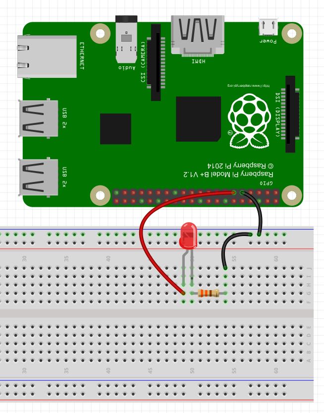
Note on the Raspberry Pi, the output voltage is 3.3 volts as opposed to the 5 volt output on the Arduino. Hence, the Raspberry Pi can only simulate analog voltages between 0 and 3.3 volts. For this example, we will be playing with the following circuit again. Note we are using physical pin 9 as the ground and physical pin 11 as the power pin. See Lesson 25 below for a diagram of pin numbers on the Raspberry Pi.
OK, enough background, lets start playing with some code. On examples like this, I think it is easiest to operate from the Python Shell, as this allows us to observe the effects of our commands one at a time. To enter the Python Shell, type sudo python at the linux command line in a terminal window. The sudo is important as it allows you to enter the python shell as a superuser. Access to the GPIO pins requires superuser privileges. Also, remember that to exit the python shell and return to the Linux command prompt you enter Ctrl-d. So, type in sudo python to go to the python shell. You should see the >>> prompt indicating you are not in the python shell. The first thing you need to do is import the RPi library:
>>> import RPi.GPIO as GPIO
Now tell the Raspberry Pi which pin number scheme you want to use (See Lesson 25). I prefer to use the physical pin numbering system as I find it easier to remember. To use the physical pen numbering system, you would enter this command:
>>> GPIO.setmode(GPIO.BOARD)
Note, if you prefer the BCM system, replace BOARD with BCM in the command above.
Now we need to tell the Pi that physical pin 11 will be an output. We can do that will the command:
>>> GPIO.setup(11,GPIO.OUT)
At this point we could write the pin high or low, but our objective here is to use PWM, so we need to do a few more things. First, we need to create a PWM object. I will call my object my_pwm. We will need to pass the parameters of the physical pin we want to use, and the frequency. I like to use 100 Hz, which gives us a period of 10 msec. The command we need for this is:
>>>my_pwm=GPIO.PWM(11,100)
Remember capitalization needs to be EXACT! Now to start the pwm we need to decide what DutyCyle we want. Remember, the DutyCycle is the percentage of the period that the signal will be high. If we wanted to approximate a 1.6 volt signal, we would note that 1.6 is about half of the 3.3 coming out of the Pi, so we would want a 50% duty cycle. The command for this would be:
>>>my_pwm.start(50)
When you type this command you should see the LED come on, if you have connected things correctly. It should be at about half brightness.
Now if you would like to change the brightness, just change the Duty Cycle. For example, if you wanted the LED very dim, you might set a 1% duty cycle. You could do this with the command:
>>>my_pwm.ChangeDutyCycle(1)
Similarly, if you wanted full brightness, you would want a 100% duty cycle, which you could get with the command:
>>>my_pwm.ChangeDutyCycle(100)
Again, please remember that the capitalization has to be exact. Now you can get any brightness you want by changing the duty cycle to anything between 0 and 100, inclusive.
Note you can also change the frequency of the PWM signal. Lets say you wanted a frequency of 1000 Hz. We could do this with the command:
>>>my_pwm.ChangeFrequency(1000)
Note that by doing this there is no perceptible change in LED brightness because you have not changed the relative on and off time of the signal. You are just going faster, but not impacting the fractional time the signal is on and off, hence the LED brightness does not change.
While in these examples we have done things from the control line, you can write python programs that will run the commands for you. For example, write a program that asks the user how bright he wants the LED, between 0 and 100, and then set it to that brightness by adjusting the Duty Cycle, as we did in the example above. Play around with different pins and different frequencies and values. Become familiar with these commands.
Now, finally, if you want to turn pwm off, you would use the command:
>>>my_pwm.stop()
Also, remember that you should always clean up after yourself, so at the bottom of your program, or before you exit the shell, always release your pins and clean up using the command:
>>>GPIO.cleanup()
Lesson 8: Writing Analog Voltages in Arduino
We have done some pretty cool stuff so far with the arduino. We have learned how to get input from the user, and how to send information to the user. We have learned how to control commands with both for loops and while loops. We are well on our way to building some really powerful projects. The thing is, so far all of our commands to the arduino pins have in effect been to either turn the pin On or turn it Off. That is, when we digitalWrite HIGH or LOW to the pins, we are either turning on the full 5 volts or turning it all the way off. The truth is that most times we want something in the middle. We would maybe want a voltage of 2.3 volts.
The arduino pins with the squiggly line by them are able to write these in between voltages. These are pins 3,5,6,9,10,11 on the arduino uno.
In the world of engineering and electronics, we say that we want an analog voltage. That is, we want to apply any voltage we want, not just 0 or 5. To output an arbitrary voltage between 0 and 5, would issue the arduino an analogWrite command. Unfortunately, the arguments for the analogWrite command are not as simple as telling it a number between 0 and 5. We must give it an integer between 0 and 255. If we issued the command analogWrite(mypin,0), it would apply 0 volts to mypin. If we issued the command analogWrite(mypin,255), it would appy 5 volts to the pin. As you can see, if we gave the command analogWrite(mypin, 127), we would get about 2.5 volts applied to mypin. You can see those are the easy ones, but in order to figure out exactly what value we should use for exactly the voltage we want, we will need to do some math. Remember all the times you had to calculate the equation of a line in math? Well you are going to do it for real now and for a reason. We need to get an equation that will allow us to calculate the Write Value we should use to get the Voltage

You can see that you need the equation for the line above. Good news! You have two points so can calculate the equation of the line. The first point is (0,0), that is to say, that if you want a voltage of 0 to be applied to the pin, you should analogWrite the value of 0, as we explained above. The second point is (5,255), that is to say, if you want to apply a voltage of 5 Volts, you should analogWrite the value 255, as explained above. Now we calculate the equation of the line. the slope would be:
m = (y2-y1)/(x2-x1) = (255-0)/(5-0) = 51
OK, now to get the equation of the line we will use the point slope form of a line, and we get:
(y-y1)=m(x-x1)
We can plug in the point (0,0) and get
(y-0) = m(x – 0)
And when we plug in 51 for m we get:
y = 51X
Remember X is the voltage we want, and Y is the value we write, so this equation can be rewritten:
Write Value = 51 X (Desired Voltage)
So, this equation lets us calculate precisely what value we should analogWrite in order to get the voltage we want on the pin. I hope this makes sense. If you are confused watch the video and it will make more sense.
The bottom line is that we can use this equation to calculate the number we should write to get the voltage that we want at a pin.
As an example, if we wanted to get exactly 2 volts, we should write the value 2X51= 102. If we wanted two volts on the pin myPin, we would issue the command analogWrite(mypin, 102).
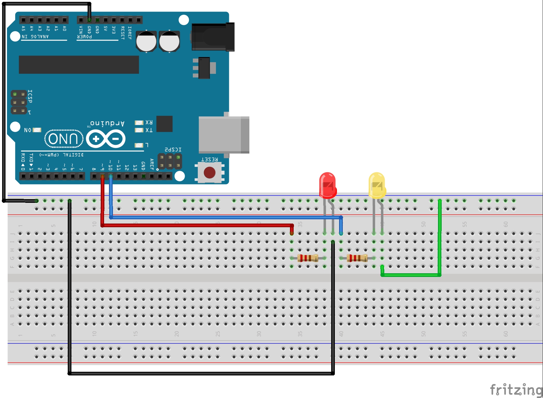
Now lets start playing around with a circuit. Lets use the circuit we have been using the last few lessons. Hopefully you still have it hooked up, but if you need help we take you through it step-by-step in Lesson 3.
Lets start with our code from Lesson 7:
1 2 3 4 5 6 7 8 9 10 11 12 13 14 15 16 17 18 19 20 21 22 23 24 25 26 27 28 29 30 31 32 33 34 35 36 37 38 39 40 41 42 43 44 45 46 47 48 | int redLEDPin=9; //Declare redLEDPin an int, and set to pin 9 int yellowLEDPin=10; //Declare yellowLEDPin an int, and set to pin 10 int redOnTime=250; //Declare redOnTime an int, and set to 250 mseconds int redOffTime=250; //Declare redOffTime an int, and set to 250 int yellowOnTime=250; //Declare yellowOnTime an int, and set to 250 int yellowOffTime=250; //Declare yellowOffTime an int, and set to 250 int numYellowBlinks; //Number of times to blink yellow LED int numRedBlinks; //Number of times to blink red LED String redMessage="The Red LED is Blinking"; //Declaring a String Variable String yellowMessage= "The Yellow LED is Blinking"; //Declaring a String Variable void setup() { Serial.begin(115200); // Turn on the Serial Port pinMode(redLEDPin, OUTPUT); // Tell Arduino that redLEDPin is an output pin pinMode(yellowLEDPin, OUTPUT); //Tell Arduino that yellowLEDPin is an output pin Serial.println("How Many Times Do You Want the Red LED to Blink? "); //Prompt User for Input while (Serial.available()==0){ } //Wait for User Input numRedBlinks = Serial.parseInt(); //Read User Input Serial.println("How Many Times Do You Want the Yellow LED to Blink? "); //Prompt User for Input while (Serial.available()==0){ } //Wait for Input numYellowBlinks = Serial.parseInt(); //Read User Input } void loop() { Serial.println(redMessage); for (int j=1; j<=numRedBlinks; j=j+1) { // Start our for loop Serial.print(" You are on Blink #: "); Serial.println(j); digitalWrite(redLEDPin,HIGH); //Turn red LED on delay(redOnTime); //Leave on for redOnTime digitalWrite(redLEDPin,LOW); //Turn red LED off delay(redOffTime); //Leave off for redOffTime } Serial.println(" "); Serial.println(yellowMessage); for (int j=1; j<=numYellowBlinks; j=j+1) { // Start our for loop Serial.print(" You are on Blink #: "); Serial.println(j); digitalWrite(yellowLEDPin,HIGH); //Turn yellow LED on delay(yellowOnTime); //Leave on for yellowOnTime digitalWrite(yellowLEDPin,LOW); //Turn yellow LED off delay(yellowOffTime); //Leave off for yellowOffTime } Serial.println(" "); } |
If you have been following these lessons, this code should make sense as we have built up step by step.
What we need to do now is to replace the four digitalWrite commands with analogWrite commands. Lets say that instead of applying 5 volts to the LED we want to apply 1 volt. This should make the LED’s blink noticeably dimmer. Remember that we would not analogWrite a value of 1, but need to calculate the write value from our formula. We want a voltage of 1 volt, so our write value should be 1 X 51, or the value 51. So now instead of digitalWrite, we should have a command like analogWrite(redLEDPin, 51) or analogWrite(yellowLEDPin, 51). Notice that on the commands that turn the LEDs off . . . digitalWrite(redLEDPin, LOW) would still work to turn the pins off, but I think it is good practice to change all the writes to analogWrites in a problem like this. To turn the pin off with an analog write would could use the command analogWrite(redLEDPin, 0).
With this new knowledge, you should modify your code and replace the 4 digitalWrite commands with analogWrite commands. Play around with writing different values to see the effect on the LED Brightness.