Tag Archives: Arduino

Arduino Tutorial 42: Understanding How to Use a Serial to Parallel Shift Register (74HC595)

74HC595
In this Circuit the 74HC595 is independently controlling 8 different LEDs.

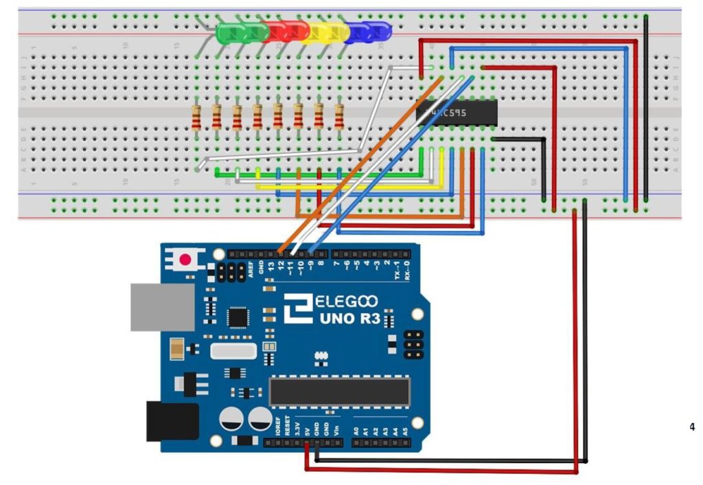
In this lesson we show you how to expand the number of LEDs or other devices you can control with the Arduino by incorporating a Serial to Parallel converter. The chip we will be using is the 74HCH595. When connected to just a few pins of the Arduino, data can be sent serially to the chip, and then LEDs can be connected to the output pins of that chip. Hence, you can control 8 LEDs using only 3 digital pins on the Arduino.

This is somewhat of a tedious project, because the circuit has lots of wires, and it must be connected perfectly. We use the following schematic in this project:

74HC595
This is the schematic we use in this example to control 8 LEDs from the 74HC595 chip.

The video takes you step by step through the entire build and programming.

The code we used in this build is included below:


9-Axis IMU LESSON 20: Vpython Visualization of Roll, Pitch, and Yaw


This is the arduino code we developed in this lesson to approximate roll, pitch and yaw over small ranges.

This is the python code we developed to visualize the 3 dimensional rotation of a rigid body.


9-Axis IMU LESSON 19: Vpython Visualization of Pitch and Yaw

To play along at home, you will need an Arduino Nano, and an Adafruit BNO055 Inertial Measurement Sensor. In this lesson we create a live visual where a 3D model rotates in space mimicking the pitch and yaw of the breadboard in the real world. We have not yet derived and implemented the math to incorporate roll into the simulation but that will ab done in the next lesson.

This is the code on the arduino side we developed in the video:

This is the code on the Python side we developed in the video:


Arduino Tutorial 41: Understanding Hexadecimal Numbers and Why They Are Important

In today’s lesson we discuss the topic of Hexadecimal numbers, and why they are important. As discussed previously, digital devices are nothing more than an incredibly large number of simple on/off switches connected together in clever ways to achieve useful functions. Since there is a need to represent numbers using only on/off switches, the binary number system is used. A switch that is in the on condition can be thought of as a “1” while a switch in the off condition can be thought of as a “0”. by stacking these switches side by side, we can represent almost any number by simply working with enough switches. As things got more complex, and the number of switches increased, it became untenable to keep up with all the 0’s and 1’s. Hence, groups of 4 switches were bunched together, and the Hexadecimal system was born. Understand Hexadecimal is simply a way to keep track of switches that is more convenient than the Binary system. This video discusses in detail, and gives lots of examples.

Arduino Tutorial 39: Using a Joystick to Control DC Motor Speed and Direction

DC Motor JoyStick
This is a simple example of how to control speed and direction of a DC motor with a joystick.

Lesson 37 and 38 showed some preliminary concepts in controlling a DC motor using an arduino and the L293D motor controller. In the video above we show how to control the speed and direction of a simple DC motor using a joystick. In the neutral position, the motor is stationary. Then the speed smoothly increases as you move the joystick forward, until you reach maximum speed.

Lesson 37 and 38 showed some preliminary concepts in controlling a DC motor using an arduino and the L293D motor controller. In the video above we show how to control the speed and direction of a simple DC motor using a joystick. In the neutral position, the motor is stationary. Then the speed smoothly increases as you move the joystick forward, until you reach maximum speed. Similarly, in pulling the joystick back from the neutral position, the motor gradually increases speed in the reverse direction. The diagram below shows the basic motor control schematic we are working from.

DC Motor Controller
Connection Diagram for a DC Motor Controller using the L293 Control Chip

In the circuit diagram above, we also add a wire to connect the arduino ground to the power supply ground. It is always good to have all components connected to a common ground rail. Of course, you also need to add the joystick controller as shown in the video.

This is the code we used in this