Tag Archives: Arduino

Arduino Tutorial 38: Using a Tilt Switch Cut Off With a DC Motor

Tilt Cut Off Switch
DC Motor circuit with a tilt switch cutoff

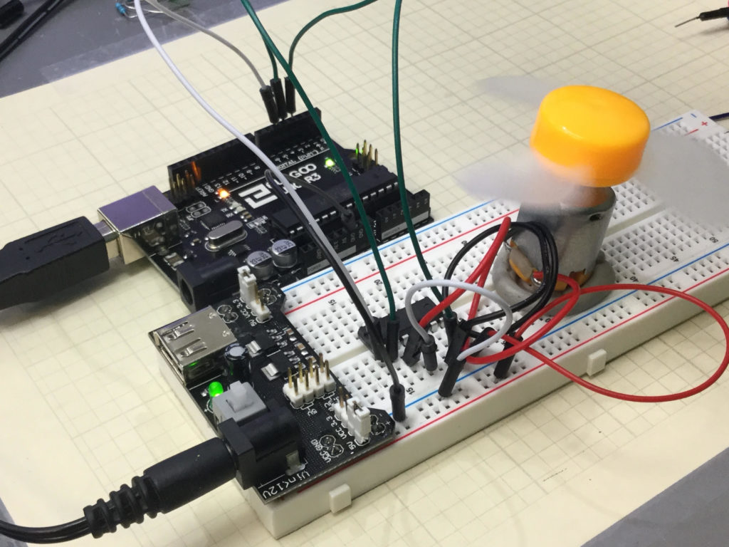
In this lesson we explore how to add a tilt cutoff to our DC motor project. In many cases, you may want to automatically turn your motors off in the case where your project or robot tips over. The tilt switch is a simple way to do this. The video below takes you through the process step-by-step.


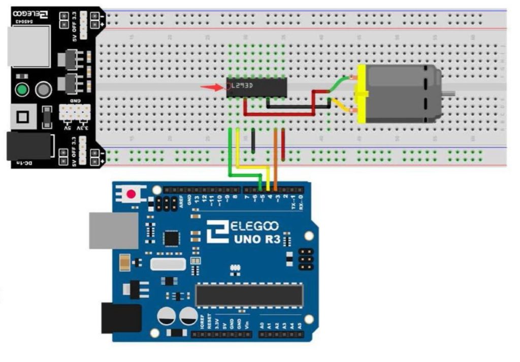
If you need help hooking the circuit up, the diagram below shows you a schematic of what we are working with. All these components are part of our ELEGOO Super Starter Kit.

DC Motor Controller
Connection Diagram for a DC Motor Controller using the L293 Control Chip

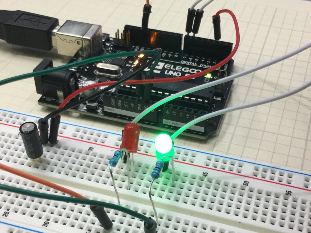
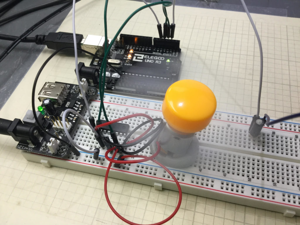
In addition, you will need to add the tilt switch, as shown in the video.

Below is the code we used, with the tilt switch connected to pin 2 on the arduino.


Arduino Tutorial 37: Understanding How to Control DC Motors in Projects

In this lesson we learn the ins and outs of controlling a DC Motor from an Arduino. A key aspect of this is to understand you must not connect a motor directly to an arduino. You need to either build a suitable transistor and diode circuit, or you need to utilize a motor controller, such as the L293D motor control chip.

DC Motor
DC Motor Controller Using the L293D control chip and an Arduino

The video below explains how to hook things up and how the code works.  You must always be mindful that you are using a motor with current requirements that are consistent with the motor controller and power supply you are working with. Failure to do so could result in damage to components or injury.

The circuit used in this video tutorial is shown below:

DC Motor Controller
Connection Diagram for a DC Motor Controller using the L293 Control Chip

It is a good practice to have all grounds connected in a circuit, so I would connect an arduino ground to the ground rail of the breadboard. The components used in this project are from the Elegoo starter kit, which you can pick up HERE. The code is described in the video, but if you need help, this is the code we used in the lesson.


Arduino Tutorial 36: Understanding How to Use Tilt Switches in Your Projects

Tilt Sensor
This Circuit Gives Visual Indicator if Board Has Been Tilted

This is a simple project that allows you to create a circuit which will give a visual indication if the breadboard has been tilted. In the upright position, the Green LED is illuminated. To the left of the board is a tilt switch. If the project is tilted, the switch will go from the closed to the open condition. This can be detected on the arduino, and then the red LED is illuminated. The video below explains how to do this simple project.

You can get the kit we are using in these lessons HERE. You should create your own code based on the instructions in the video, but if you are having trouble, I include the code developed in the video below:


Arduino Tutorial 35: Understanding How to Use a Stepper Motor

In this lesson we give you several examples of how to connect and program a stepper motor. Stepper motors are useful because they can produce very large torque at low RPM and are capable of extremely precise positioning. They are somewhat tricky to use, and you must be careful to not try and power them from an Arduino. Arduino can control stepper motors, but they must be powered from an external power supply.

If you want to follow along at home, you can order the Arduino Kit we are using HERE.

This is the code that allows you to toggle the direction of the stepper motor by pressing a pushbutton. The video shows all the details and how to connect the motor up.