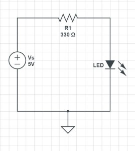
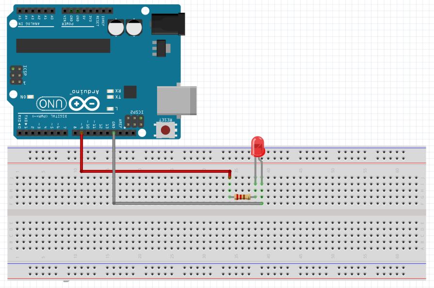
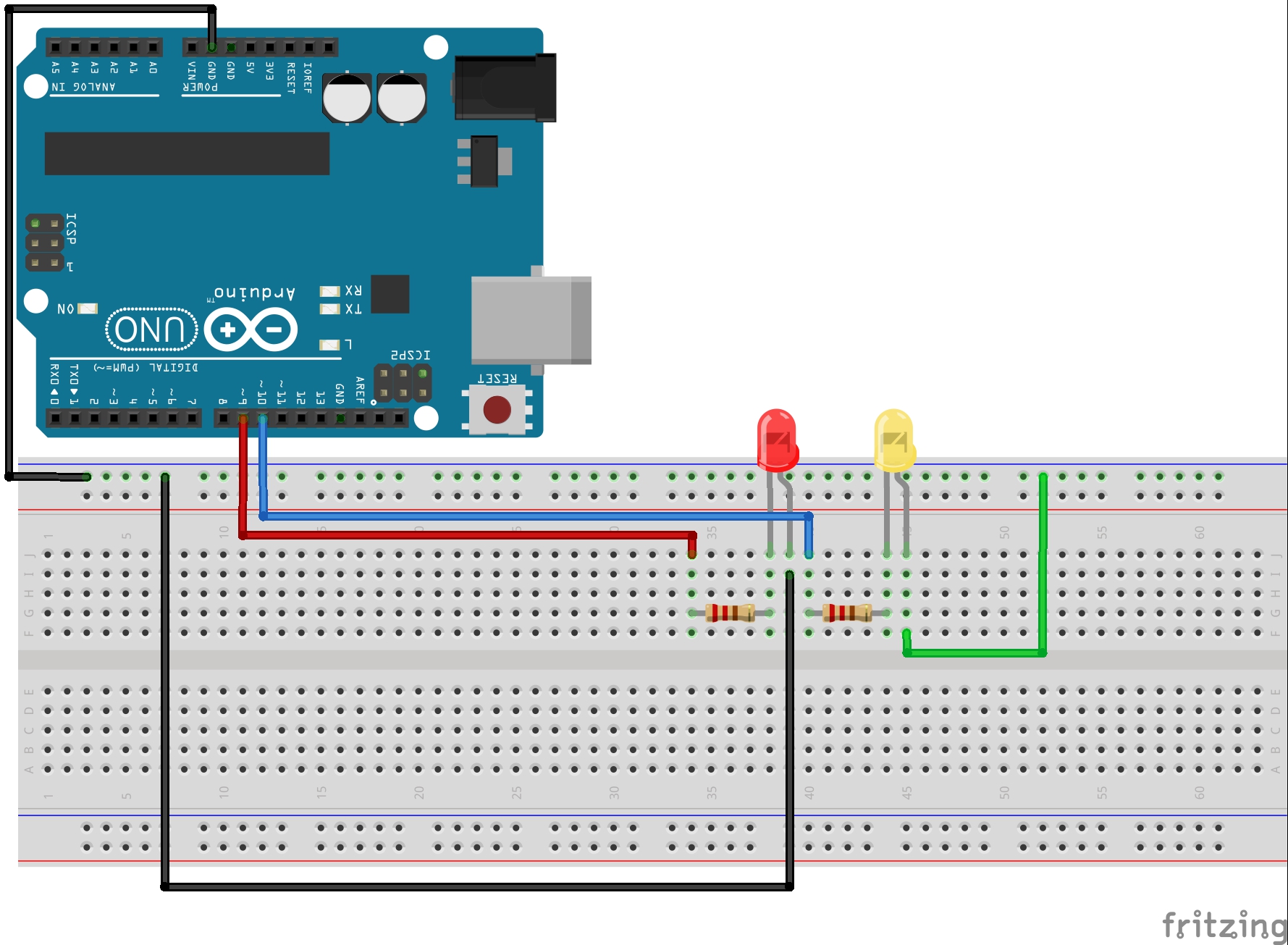
In Lesson 3 you learned about for loops, and how for loops can make your life as a programmer much simpler. You wrote a program that would blink a red LED and then a yellow LED the number of times indicated by the program. In this lesson, we will be using the same 2-LED circuit. If you don’s already have it put together, you should go ahead and do it now. This is a schematic of the circuit:
In order to independently blink the two LED’s you were probably using code similar to this:
1 2 3 4 5 6 7 8 9 10 11 12 13 14 15 16 17 18 19 20 21 22 23 24 25 26 27 28 29 30 31 | int redLEDPin=9; //Declare redLEDPin an int, and set to pin 9 int yellowLEDPin=10; //Declare yellowLEDPin an int, and set to pin 10 int redOnTime=250; //Declare redOnTime an int, and set to 250 mseconds int redOffTime=250; //Declare redOffTime an int, and set to 250 int yellowOnTime=250; //Declare yellowOnTime an int, and set to 250 int yellowOffTime=250; //Declare yellowOffTime an int, and set to 250 int numYellowBlinks=5; //Number of times to blink yellow LED int numRedBlinks=5; //Number of times to blink red LED void setup() { pinMode(redLEDPin, OUTPUT); // Tell Arduino that redLEDPin is an output pin pinMode(yellowLEDPin, OUTPUT); //Tell Arduino that yellowLEDPin is an output pin } void loop() { for (int j=1; j<=numRedBlinks; j=j+1) { // Start our for loop digitalWrite(redLEDPin,HIGH); //Turn red LED on delay(redOnTime); //Leave on for redOnTime digitalWrite(redLEDPin,LOW); //Turn red LED off delay(redOffTime); //Leave off for redOffTime } for (int j=1; j<=numYellowBlinks; j=j+1) { // Start our for loop digitalWrite(yellowLEDPin,HIGH); //Turn yellow LED on delay(yellowOnTime); //Leave on for yellowOnTime digitalWrite(yellowLEDPin,LOW); //Turn yellow LED off delay(yellowOffTime); //Leave off for yellowOffTime } } |
As you learned in Lesson 3 for loops make your program much simpler to write and much simpler to modify. In the code above, to change how many times the LED’s blink, you just have to simply change two lines of code:
1 2 | int numYellowBlinks=5; //Number of times to blink yellow LED int numRedBlinks=5; //Number of times to blink red LED |
By changing either of these variables at the top of your program, you effectively adjust how many times each LED will blink in each cycle.
Now besides just blinking the LED, it would be nice to provide some information directly to the user. It would be nice to be able to have the arduino ‘print’ information to your computer screen. You can do this by working with the Serial Port and the Serial Monitor.
In order to use the Serial Port, the first thing you have to do is turn it on inside your program. Since this is something you would only need to do once, you do it in the void setup(). The code below, when placed inside the void setup() will turn your serial port on:
1 | Serial.begin(9600); |
You will want to keep whatever else you already have going on in your void setup(), and just add the line of code above to it. Note that this line of code tells the arduino to turn the serial port on. The ‘9600’ tells the arduino to communicate at 9600 baud, which basically is just the speed you will be working at. The higher the number the faster data will be sent and received over the serial port. This can be set to different numbers, but the important thing is that everyone is talking and listening at the same speed. So, if you tell the arduino to run at 9600 baud, when you open your serial monitor later, you need to make sure it is set to the same speed.
OK, now that you have started your serial monitor you can start sending and receiving data over it. The first and easiest thing is to send data to it. We do this using Serial.print and Serial.println commands. These commands send data to the arduino serial monitor. We will show you how to open the serial monitor in a minute, but for now, lets add some print statements to our program.
1 2 3 4 5 6 7 | for (int j=1; j<=numRedBlinks; j=j+1) { // Start our for loop Serial.println(j); digitalWrite(redLEDPin,HIGH); //Turn red LED on delay(redOnTime); //Leave on for redOnTime digitalWrite(redLEDPin,LOW); //Turn red LED off delay(redOffTime); //Leave off for redOffTime } |
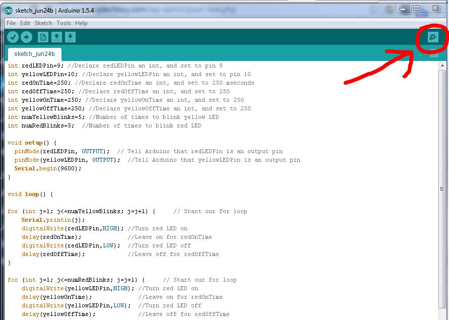
Notice that the loop above is our loop for blinking the red LED. We have added a new line to the start of the loop . . . Serial.println(j). After you add the line of code, download the code to the arduino, and then pop open your serial monitor. You do this by clicking on the magnifier icon at the upper right corner of the arduino IDE.
When you click on the icon you should see the serial monitor pop open, and you should see the values of j being printed out. It should look like this:
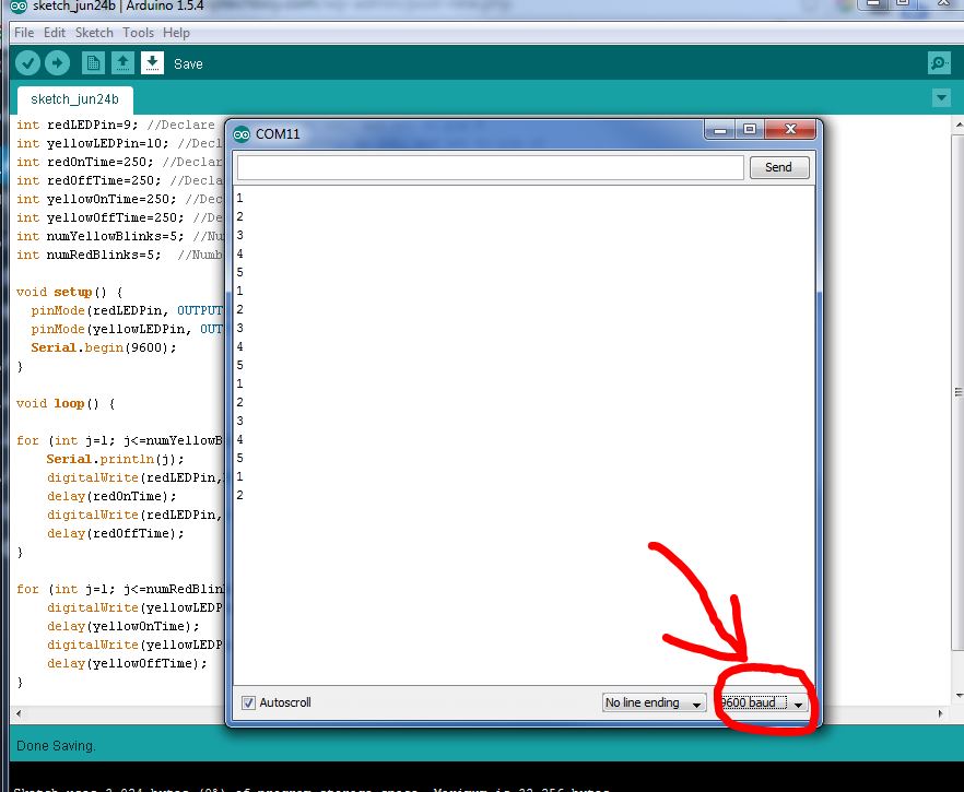
You should see the numbers printing out as your program goes through the for loop. Make sure that you have the baud rate set in the lower right corner of the serial monitor to the same value you specified in the program. 9600 baud is usually a good choice.
In the example above, we are printing the variable j each time the program loops through the for loop for the red LED. We can also print out a string of text. To print out a string of text, you put the string in quotes. To print a string you would do something like Serial.println(“Blinking Red LED”). It will print the words between the quotes. Lets add this to our code, but lets add it before the for loop, so it just prints it once each cycle. Your code for the red LED should look like this:
1 2 3 4 5 6 7 8 | Serial.println("The Red LED is Blinking"); for (int j=1; j<=numRedBlinks; j=j+1) { // Start our for loop Serial.println(j); digitalWrite(redLEDPin,HIGH); //Turn red LED on delay(redOnTime); //Leave on for redOnTime digitalWrite(redLEDPin,LOW); //Turn red LED off delay(redOffTime); //Leave off for redOffTime } |
Now download and run the code and look at your serial monitor. You should see those words printing each time before the Red LED blinks. Now go ahead and add similar code to your Yellow LED loop so that it will announce which LED is blinking and then the blink counter. Your code should look like this for the two for loops:
1 2 3 4 5 6 7 8 9 10 11 12 13 14 15 16 | Serial.println("The Red LED is Blinking"); for (int j=1; j<=numRedBlinks; j=j+1) { // Start our for loop Serial.println(j); digitalWrite(redLEDPin,HIGH); //Turn red LED on delay(redOnTime); //Leave on for redOnTime digitalWrite(redLEDPin,LOW); //Turn red LED off delay(redOffTime); //Leave off for redOffTime } Serial.println("The Yellow LED is Blinking"); for (int j=1; j<=numYellowBlinks; j=j+1) { // Start our for loop Serial.println(j); digitalWrite(yellowLEDPin,HIGH); //Turn yellow LED on delay(yellowOnTime); //Leave on for yellowOnTime digitalWrite(yellowLEDPin,LOW); //Turn yellow LED off delay(yellowOffTime); //Leave off for yellowOffTime } |
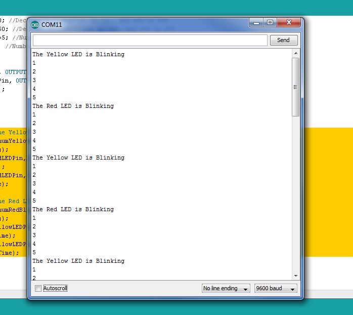
So this code will announce which LED is blinking, and will then give a count of which blink you are on. Pretty cool! Your Serial Monitor should now be looking something like this as it tells the user which LED is blinking and which blink you are on:
So we can see that we can print both variables, like j, and strings. When printing strings, it is important to include the text in quotes, so that the arduino knows you are printing the string of text, and not a variable.
Notice that each time you use Serial.println it goes to the next line. If you want to print to the same line, without advancing to the next line, you should use the command Serial.print. In the example above, lets say instead of just printing the number j, you want text in front of the number that says ‘you are on blink number ‘ and then the number. You can modify your code and add another Serial.print command to the for loops. I will do it for you on the red loop, but you need to figure out the yellow for yourself:
1 2 3 4 5 6 7 8 9 | Serial.println("The Red LED is Blinking"); for (int j=1; j<=numRedBlinks; j=j+1) { // Start our for loop Serial.print(" You are on blink number: "); Serial.println(j); digitalWrite(redLEDPin,HIGH); //Turn red LED on delay(redOnTime); //Leave on for redOnTime digitalWrite(redLEDPin,LOW); //Turn red LED off delay(redOffTime); //Leave off for redOffTime } |
You should get something that looks like this:
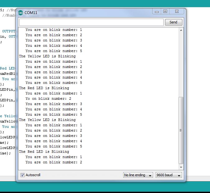
Make sure to play around with blank spaces when you print strings so that your output is neat and readable. Notice on mine that by using blank spaces I get an indent which makes the scrolling text more readable.
So, we need to carefully consider when it suitable to use Serial.print vs. when we should use Serial.println.