
In this lesson we will begin to build our first circuits that will be controlled by the Arduino. We will start out with simple circuits and build from there. It is important for you to learn the basics before moving on, and one of the most important basics is how to use a Breadboard. In this lesson we will learn the ins and outs of breadboards, and by the end of the lesson you will have your first circuit built, and it will be controlled by the arduino. Watch the video below for in depth description of how the breadboard works.
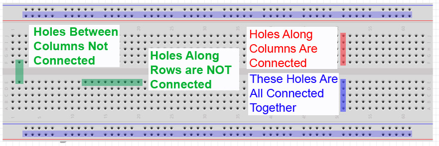
In order to build a circuit, you have to connect circuit elements together. You could run a bunch of wires to connect components, but you find that very quickly you end up with a rats nest of wires, and it becomes impossible to debug. In order to keep your circuit organized you need to use a breadboard, pictured above. The breadboard allows you to connect components together by plugging them into the little holes. The key is to understand how the holes are connected. As you can see in the diagram, the holes in a column (when oriented as shown in the picture) are connected together. So to connect components together you need to plug the leads you want connected into the same column. Note that the columns are not connected across the “trench” in the center of the board. Also notice that as the long rows at the top and bottom are connected together. These are typically used to create “rails”. These are typically used for grounds and supply voltages you might need to connect many components to. Notice some rows are marked (+) and some(-). These are just markings. The row will be set at whatever voltage YOU connect to it.
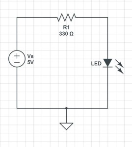
So, lets look at a real example. In this circuit we have a voltage supply connected to an LED through a resistor. We will need to take this circuit schematic and figure out how to connect it up in the real world. As mentioned above this should be done using a breadboard. You can see that you need to connect the voltage supply to one leg of the resistor. The other leg of the resistor is connected to the LED. Note that the LED is directional, meaning it has to be connected in a certain orientation. You must connect the Cathode to the positive voltage. The Cathode is typically the longer of the two leads on the LED. If you put the LED in upside down, it will not light up. The other leg of the LED needs to be connected to the negative terminal of the voltage supply. For this project we will supply the voltage from the Arduino microcontroller. That way, we can turn the LED on and off from our program.
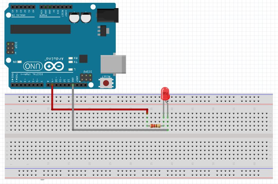
Look at the diagram at the top of this post to see how the holes are connected in the breadboard, and figure out a way you could connect the circuit up using the PC board. There are many ways to hook it up, but one that will work is shown here.
When you hook your circuit up in real life, it should look something like this:
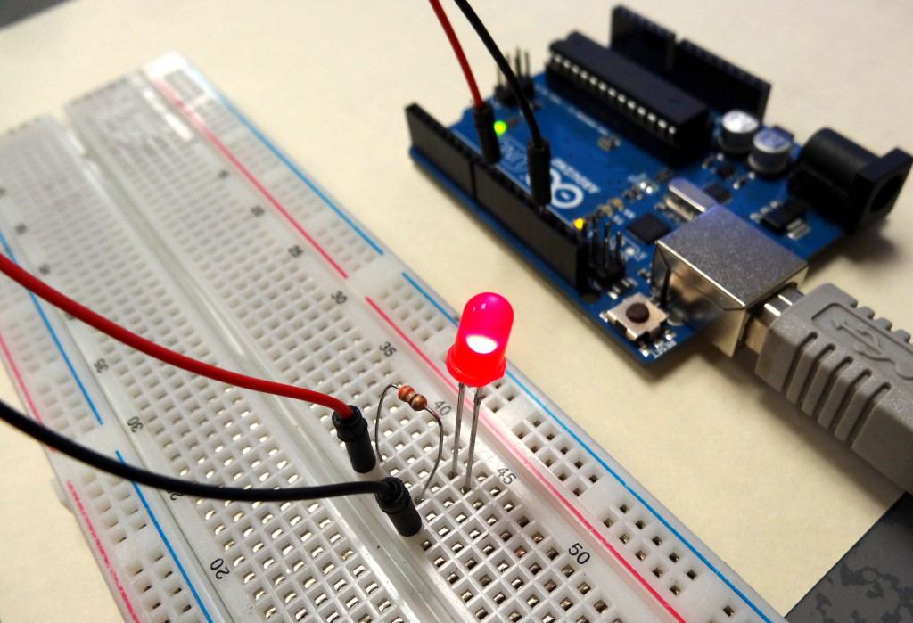
Remember that it is the long leg of the LED that is connected to the resistor and the short leg to the black wire going to ground.
Now, if you follow along and develop the code as outlined in the video you should be able to do amazing things with the LED.
RESOURCES: On all these lessons I will include resources on where you can purchase the items mentioned in the lecture.
Arduino Microcontroller![]() : You can get a good deal on the arduino on Amazon. Arduinos are open source and many are cheap chinese knockoffs, so you want to make sure you get an “official” version, which you can at the link above.
: You can get a good deal on the arduino on Amazon. Arduinos are open source and many are cheap chinese knockoffs, so you want to make sure you get an “official” version, which you can at the link above.
Arduino Beginner’s Kit: While the bare arduino will get you started, I really suggest getting the complete Beginner’s Kit. The projects I will feature in this tutorial set will use the components in this kit, and it is probably cheaper to go ahead and get the kit than to buy the individual components as you go along. The kit is under $100 on Amazon.